


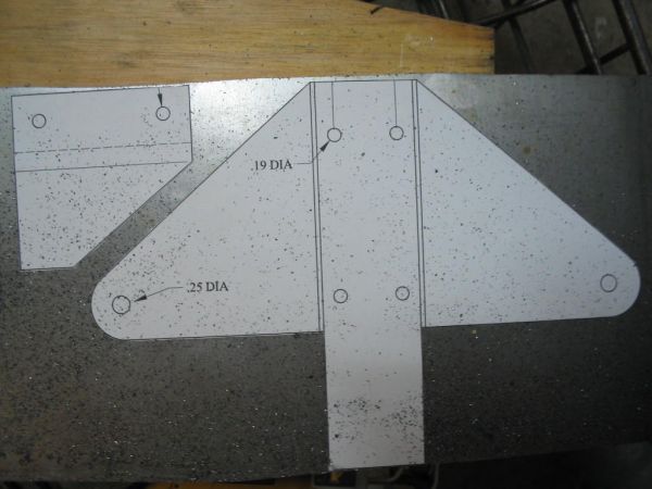
Page 7 has the dimensions and drawing for the bellcrank bracket. I know many of you will buy your wing hardware from Steen, but since I decided to make everything on this plane, here's my process for the Bellcrank Bracket.
First, I drew the part on a CAD program, printed it, and cut it out and glued it to the .063 4130 steel sheet. This makes for a more accurate piece when cutting out.
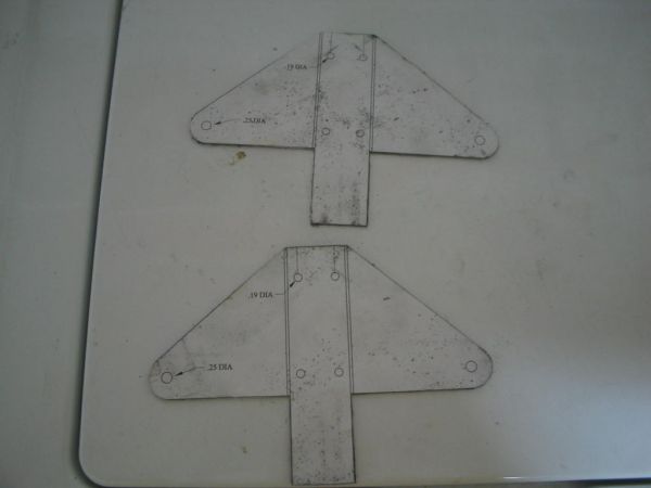
I use a jigsaw to cut because I LIKE my jigsaw. You may use a hacksaw, band saw, etc. After cutting, I finish to final dimension on the belt sander using a 50 grit belt.
Now, as Randy has previously mentioned, you should NOT USE the same belt sander as the one you use on wood. The buildup of sawdust is prime kindling for a fire from a metal spark. It ain't worth loosing your house to a beltsander, so use caution.
As you can see by the above pic, I was also cutting out the pieces for my aileron hinges. I'll get back to them later. The next pic shows the piece after cutting and final dimensioning on the belt sander:
Don't drill any of the holes at this time.
If you look at your drawings on pg7 of the plans, you'll see that it shows the (roughly) 2"x2" piece (what looks like a tail in the above pic) as a separate, welded-in piece. I am doing mine differently, but some steps must be taken when welding. We'll discuss later.
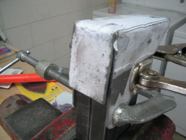
Next is a pic of the bending blocks and vice I was using to bend that tail into place.
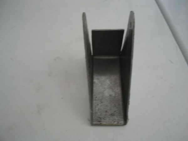
This piece must be dimensioned properly so as to fit BETWEEN the two sides, not OVER them. You'll end up with something like this:
Then it's time to weld the pieces together. Remember what I said about something important? Well this is it: When you bend that tail piece into place, if you look carefully in the corners where the three pieces meet, you'll see what looks like a hole that forms, because this is where the two bends (on each side) meet. This little hole is a prime place for a crack to form.
When welding, weld on the outside and make sure you go into the corner and use filler to blend and close that hole. Penetration is important here, because adequate penetration and use of filler will eliminate the stress area around the hole.
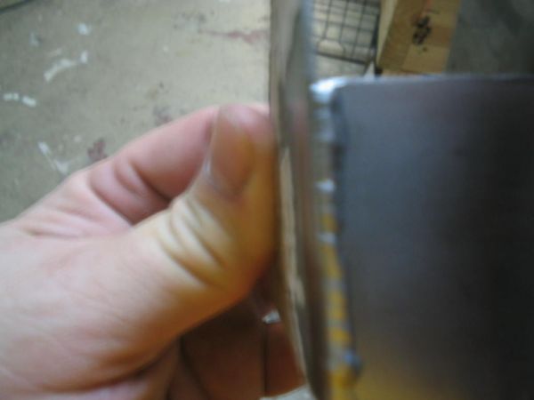
If you are using a torch or tig, you really don't need to use filler rod on this seem weld if you don't wish to. I chose to use it, but used .035 rod so that I did not use too much. Here is my weld:
ANy Q's or comments....??
It is now the time to finish drilling the holes. I will drill and post pics of the finished product soon.