


Ok, previously I posted a bearing collar that was constructed similar to the MacKenzie newsletter designs. That bearing collar has limitations, such as maintenance....it cannot be removed for cleaning or lubrication once installed on the torque tube. Also, the torque tube must be micro-ground to proper size to fit the bearing. it has many positive aspects of the design...however, being one that likes to experiment, I will try something different in a later posting. I am building two torque tubes and will use the one that I like the best, hence the picture of four thrust collars.
This post will show something different for the thrust collar. As detailed by Neil Sidders in his article for Acrosport Mods, the Skybolt plans call for a 1 3/4" x .058 tubing, 3/8" wide, to be welded to the torque tube to act as a thrust collar. Neil had some concerns about wear int his area....concerns I share 100%...so Neil made some wider thrust collars. I will detail the same here, using a bit different process. His process was very good, mine is just a bit different.....use your judgement on which you would like to pursue.
I started by cutting out some rings from .125 4130. I am using this thick material for a reason, as I will show below.
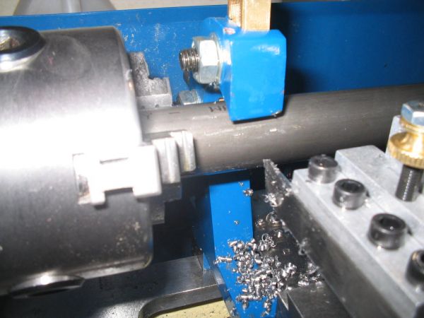
I decided to make this as simple as possible, doing it in a way that requires minimal tooling and time. First, I cut some 1 3/4" .058 tubing into sections 1" wide. I used a lathe and a parting bit so that I could get this cut as straight as possible. You could also use a saw, then cut the face in the lathe.
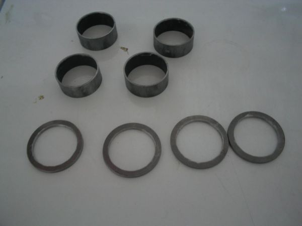
I then went to my drill press and using a 1 5/8" hole saw, bored a hole in the .125 4130 steel. Without moving the steel plate, I then switched the hole saw to a 2 1/8" size. It produces a ring that is roughly .225 wide at the face. I ended up with these:
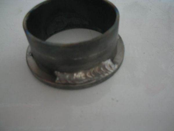
I then welded the rings on the end of the 1 3/4" tubing pieces. I used a piece of 1 5/8" tubing as a guide. Ensure the rings sit flat against the edge of the tubing. Tack weld them in 4 places, 90deg apart. Then go back and weld a bead app. 1" long, in two places, 180deg apart. I did not think it necessary to weld the perimeter of the ring, as the 1 3/4" tubing will only be subjected to compression loads against the ring, not pulling away from the ring. I ended up with this:
After welding, the ring and the tubing will distort from the heat.Neil used silversolder to keep the heat distortion to a minimum. For those not familiar, silversolder (more appropriately called "silver brazing") uses a material that melts at a lower temp than brass brazing rod, but at higher temps than tradtional electronic or plumbing solder. I've used this material to make cable ends on motorcycles, but did not feel comfortable using it on my control system.
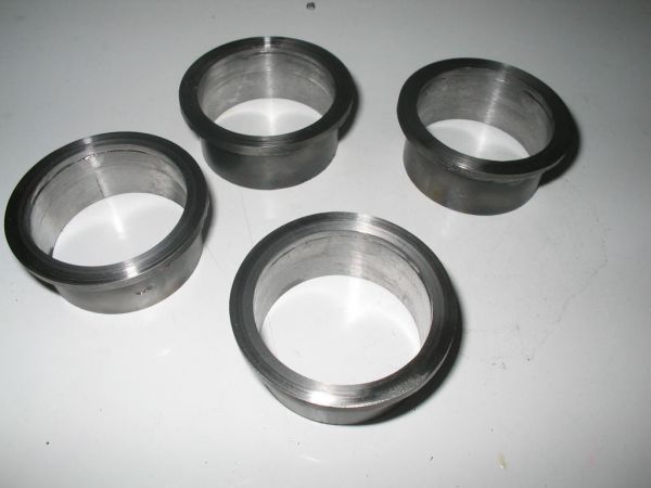
Since the parts were now distorted, I used my lathe to "fix" this. I used a boring bar to remove .010 from the inside of the 1 3/4" tubing, which brought itback to round shape.It also allowed for a better fit when sliding it on the 1 5/8" tubing, because as it exists it is an interference fit. I then removed about .020 from the face of the thrust ring, using a very slow feed to create a very smooth, straight surface. This is the reason for the .125 material....after facing, there is still .100 left, plenty enough to be durable, and close to what Neil used for his rings.
This is what I got:
You can then slide the collars on the torque tube and tack weld the collar at the very edge of the 1 3/4" tubing. This will keep the heat at least 1" away from the bearing surface of the torque tube.
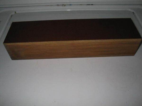
In my next post, I am going to attempt to build a bearing block from phenolic...Norplex-Micarta brand. Here's a big chunk of it that I just picked up cheap....$10.
Stay tuned.....Edited by: scottly
This post will show something different for the thrust collar. As detailed by Neil Sidders in his article for Acrosport Mods, the Skybolt plans call for a 1 3/4" x .058 tubing, 3/8" wide, to be welded to the torque tube to act as a thrust collar. Neil had some concerns about wear int his area....concerns I share 100%...so Neil made some wider thrust collars. I will detail the same here, using a bit different process. His process was very good, mine is just a bit different.....use your judgement on which you would like to pursue.
I started by cutting out some rings from .125 4130. I am using this thick material for a reason, as I will show below.
I decided to make this as simple as possible, doing it in a way that requires minimal tooling and time. First, I cut some 1 3/4" .058 tubing into sections 1" wide. I used a lathe and a parting bit so that I could get this cut as straight as possible. You could also use a saw, then cut the face in the lathe.
I then went to my drill press and using a 1 5/8" hole saw, bored a hole in the .125 4130 steel. Without moving the steel plate, I then switched the hole saw to a 2 1/8" size. It produces a ring that is roughly .225 wide at the face. I ended up with these:
I then welded the rings on the end of the 1 3/4" tubing pieces. I used a piece of 1 5/8" tubing as a guide. Ensure the rings sit flat against the edge of the tubing. Tack weld them in 4 places, 90deg apart. Then go back and weld a bead app. 1" long, in two places, 180deg apart. I did not think it necessary to weld the perimeter of the ring, as the 1 3/4" tubing will only be subjected to compression loads against the ring, not pulling away from the ring. I ended up with this:
After welding, the ring and the tubing will distort from the heat.Neil used silversolder to keep the heat distortion to a minimum. For those not familiar, silversolder (more appropriately called "silver brazing") uses a material that melts at a lower temp than brass brazing rod, but at higher temps than tradtional electronic or plumbing solder. I've used this material to make cable ends on motorcycles, but did not feel comfortable using it on my control system.
Since the parts were now distorted, I used my lathe to "fix" this. I used a boring bar to remove .010 from the inside of the 1 3/4" tubing, which brought itback to round shape.It also allowed for a better fit when sliding it on the 1 5/8" tubing, because as it exists it is an interference fit. I then removed about .020 from the face of the thrust ring, using a very slow feed to create a very smooth, straight surface. This is the reason for the .125 material....after facing, there is still .100 left, plenty enough to be durable, and close to what Neil used for his rings.
This is what I got:
You can then slide the collars on the torque tube and tack weld the collar at the very edge of the 1 3/4" tubing. This will keep the heat at least 1" away from the bearing surface of the torque tube.
In my next post, I am going to attempt to build a bearing block from phenolic...Norplex-Micarta brand. Here's a big chunk of it that I just picked up cheap....$10.
Stay tuned.....Edited by: scottly