


Ok, here I will show the fabrication of my Idler Support Bracket, shown on plans page 14. If I miss any steps that you can see, please chime in and let me know.
I first start by laying out the image on my CAD program. I cut it out and use spray adhesive to affix the image to the .063 4130 steel sheet that I have. My bracket is drawn and fabricated different than plans. The plans show the "shorter" sides (sides without arch or holes) are separate pieces that are welded in place on three sides.
My brakets are different...I cut to shape so that ALL 4 sides would be bent into place, and the corners welded together.
SInce the plans method would have you placing the two bends with the direction of the grain, I chose those same two bends to place in the direction of the grain, as shown by the arrows. The other two additional bends (the ones I added) go against the grain. I chose this method because the two bends called for in the plans are the most critical (stress bearing) and the most likely to develop a crak if they went against the grain.
In my pic below, you can also see that I made the added sides the LONGER of the four sides so that they would press up against the OUTSIDE of the two stress bearing sides. I did this because the heat from welding will try to distort the metal, and if these added sides are outside, they will distort AWAY from the stress bearing sides, instead of forcing the stress bearing sides out of proper alignment. Follow me so far?
The circles on the pics show where I drilled a very small hole at the end of the cut. Thsi is to keep the material from cracking while bending. Keep in mind that this total piece is only 2" square OD, so it may be hard to see the holes.
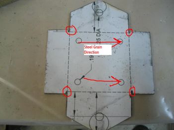
The big circles are only for a reference....I used them to experiment with the size of the radius at the arch, since the plans don't list it. I settled on 1/2" radius.
The next pic shows the corners before bending. It's kinda blurry, but you can see the rounded edge made from the small drill bit. No cracks allowed here!
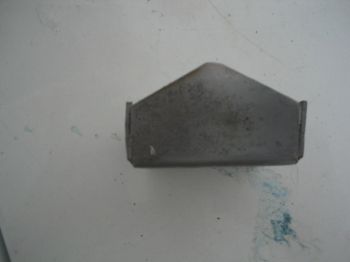
You then use a bending block to bend all four sides into place. I like to use steel bending blocks and it just so happens that I have a piece of square steel that is 1 7/8", perfect for bending. Since there is no radius listed for the bend, it is always safe to use a radius about the same dimension as the material thickness. 1/16" will work great on this piece. Below is the result. The paper has been removed due to the upcoming welding process.
You then fire up the TIG machine or torch, and do your thing. It is important to note that when welding these up, the corners where you drilled the small holes must be filled in, and penetration must be sufficient to prevent any stress cracking. The result is the next pic:
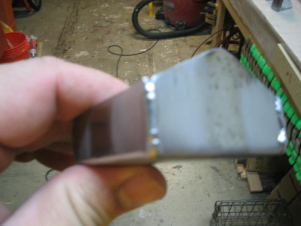
If you are using a torch or tig, you really don't need to use filler rod on this seem weld if you don't wish to. I chose to use it, but used .035 rod so that I did not use too much.
You can now drill the holes as called for in the plans. i will print another CAD drawing and glue it on as a template.
Happy building!!!Edited by: scottly
I first start by laying out the image on my CAD program. I cut it out and use spray adhesive to affix the image to the .063 4130 steel sheet that I have. My bracket is drawn and fabricated different than plans. The plans show the "shorter" sides (sides without arch or holes) are separate pieces that are welded in place on three sides.
My brakets are different...I cut to shape so that ALL 4 sides would be bent into place, and the corners welded together.
SInce the plans method would have you placing the two bends with the direction of the grain, I chose those same two bends to place in the direction of the grain, as shown by the arrows. The other two additional bends (the ones I added) go against the grain. I chose this method because the two bends called for in the plans are the most critical (stress bearing) and the most likely to develop a crak if they went against the grain.
In my pic below, you can also see that I made the added sides the LONGER of the four sides so that they would press up against the OUTSIDE of the two stress bearing sides. I did this because the heat from welding will try to distort the metal, and if these added sides are outside, they will distort AWAY from the stress bearing sides, instead of forcing the stress bearing sides out of proper alignment. Follow me so far?
The circles on the pics show where I drilled a very small hole at the end of the cut. Thsi is to keep the material from cracking while bending. Keep in mind that this total piece is only 2" square OD, so it may be hard to see the holes.
The big circles are only for a reference....I used them to experiment with the size of the radius at the arch, since the plans don't list it. I settled on 1/2" radius.
The next pic shows the corners before bending. It's kinda blurry, but you can see the rounded edge made from the small drill bit. No cracks allowed here!
You then use a bending block to bend all four sides into place. I like to use steel bending blocks and it just so happens that I have a piece of square steel that is 1 7/8", perfect for bending. Since there is no radius listed for the bend, it is always safe to use a radius about the same dimension as the material thickness. 1/16" will work great on this piece. Below is the result. The paper has been removed due to the upcoming welding process.
You then fire up the TIG machine or torch, and do your thing. It is important to note that when welding these up, the corners where you drilled the small holes must be filled in, and penetration must be sufficient to prevent any stress cracking. The result is the next pic:
If you are using a torch or tig, you really don't need to use filler rod on this seem weld if you don't wish to. I chose to use it, but used .035 rod so that I did not use too much.
You can now drill the holes as called for in the plans. i will print another CAD drawing and glue it on as a template.
Happy building!!!Edited by: scottly