


Ok...the usual disclaimer. I decided to build a tailwheel based on some designs I saw available on the market.If you ain't sure this is gonna work on your plane, don't build it. Build it at your own risk.
Ok, I see several ways to make the first piece of this assembly. A good choice is 2" 4130 tubing with .250 wall. However, since most suppiers seem to be out of this, I decided to use some 1018 round bar I had laying around. Yes, solid round bar.
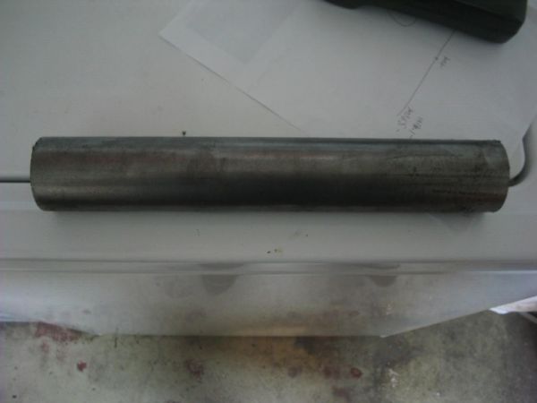
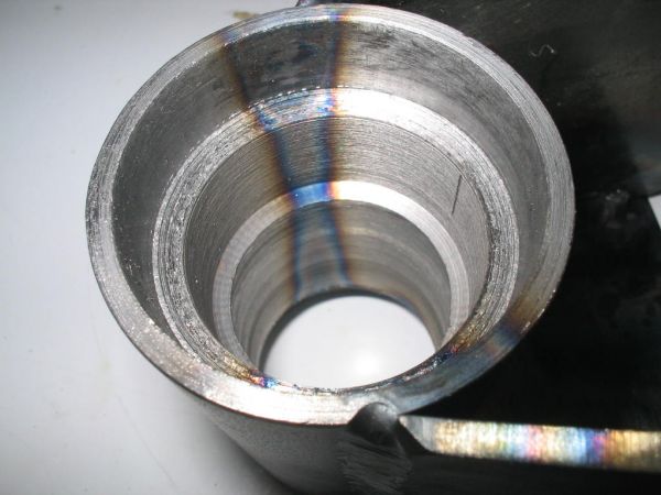
I chucked it in a lathe and drilled to1". I used a boring bar to take it the rest of the way out. The piece is sized for a 1633 bearing. I will be using a shielded bearing. The dimensions of this bearing are 5/8" x 1 3/4" x .500
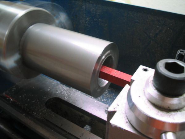
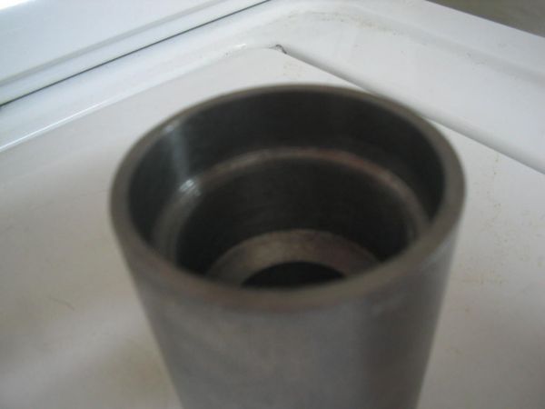
If you look at the next pic, it gives the appearance that I left the center portion of this piece in a very thick state. Not true.... I left a narrow (.050) ringin the tube so that the center bearing spacer couldn't drift too far to the side so that I couldn't get the axle to engage it. Does that make sense?")
Anyway, here's the finished product:
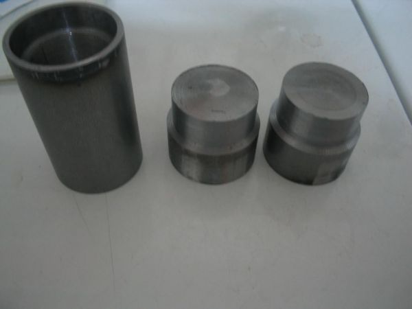
Next order of business was to machine a couple of welding plugs. When I get to the step where I weld the side plates on it, the side plates are .125 4130, so A LOT of heat will be exchanged and will cause the machined surface todistort. Welding plugs pressed into the bearing cavity will prevent this.
The side plates were drawn on CAD and cut from .125 4130. I did not drill the axle hole until AFTER I welded these. In the next pic, you can see the heat signature that penetrated the machined bar.
The top support plate is welded from the underside. This is because the assembly will swivel under the locking mechanism, and any weld on the top will impede the ability of the piece to do this. If the welds are grinded flat, it will significantly affect the strength of the weld. So, underside it is:
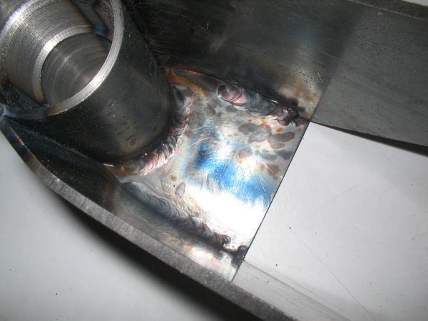
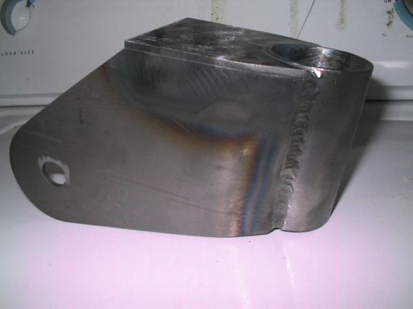
Here is the assembly after welding:
I am using a 6" tailwheel. The wheel is solid and is rated for 450lbs. Other examples I have seen of this piece use a 5" tailwheel, but Steen Aero uses this 6" tailwheel, with a different mount. I decided to stick to this wheel.....your mileage may vary.
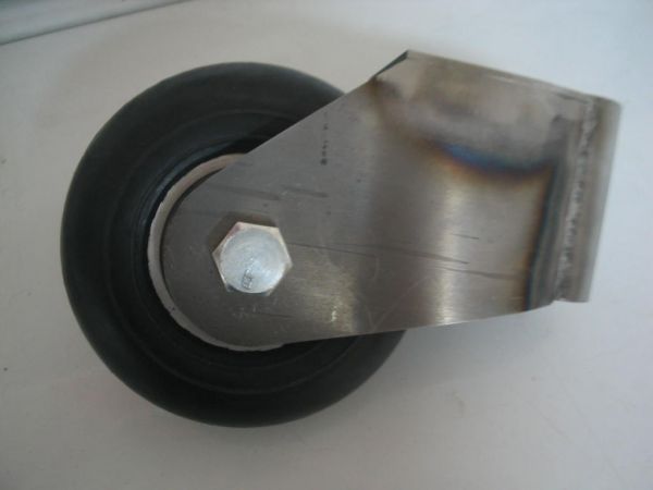
It has a 5/8 axle.
In Part 2 I will show how I made the top piece. That will have to wait until next week....
Edited by: scottly
Ok, I see several ways to make the first piece of this assembly. A good choice is 2" 4130 tubing with .250 wall. However, since most suppiers seem to be out of this, I decided to use some 1018 round bar I had laying around. Yes, solid round bar.
I chucked it in a lathe and drilled to1". I used a boring bar to take it the rest of the way out. The piece is sized for a 1633 bearing. I will be using a shielded bearing. The dimensions of this bearing are 5/8" x 1 3/4" x .500
If you look at the next pic, it gives the appearance that I left the center portion of this piece in a very thick state. Not true.... I left a narrow (.050) ringin the tube so that the center bearing spacer couldn't drift too far to the side so that I couldn't get the axle to engage it. Does that make sense?
Anyway, here's the finished product:
Next order of business was to machine a couple of welding plugs. When I get to the step where I weld the side plates on it, the side plates are .125 4130, so A LOT of heat will be exchanged and will cause the machined surface todistort. Welding plugs pressed into the bearing cavity will prevent this.
The side plates were drawn on CAD and cut from .125 4130. I did not drill the axle hole until AFTER I welded these. In the next pic, you can see the heat signature that penetrated the machined bar.
The top support plate is welded from the underside. This is because the assembly will swivel under the locking mechanism, and any weld on the top will impede the ability of the piece to do this. If the welds are grinded flat, it will significantly affect the strength of the weld. So, underside it is:
Here is the assembly after welding:
I am using a 6" tailwheel. The wheel is solid and is rated for 450lbs. Other examples I have seen of this piece use a 5" tailwheel, but Steen Aero uses this 6" tailwheel, with a different mount. I decided to stick to this wheel.....your mileage may vary.
It has a 5/8 axle.
In Part 2 I will show how I made the top piece. That will have to wait until next week....
Edited by: scottly