


Ok...Here is the second half of this build I am doing. For the record, this part is heavy. The completed assembly pictured at the bottom of this post is 8lbs, 6oz. I have to put this part on a diet. I ordered some titanium hardware to save a few oz's on those large bolts you see, and am looking for a lighter wheel that meets the same weight specs. I think Matco has one that is about 12oz's lighter.
My goal was to get this thing as light as a Scott 3200, which is about 7lbs.... but the Scott 3200 uses a heavier leaf spring and I am using spring rod. If I can get my wheel to 7lbs, I'll be a happy camper.
I think it is as heavy as it is because of the bulky material I used. Since I am not an engineer and don't know about stress analysis, I built this thing with great amount of overkill in mind. I know it's safe, it's just heavier than I'd like it to be.
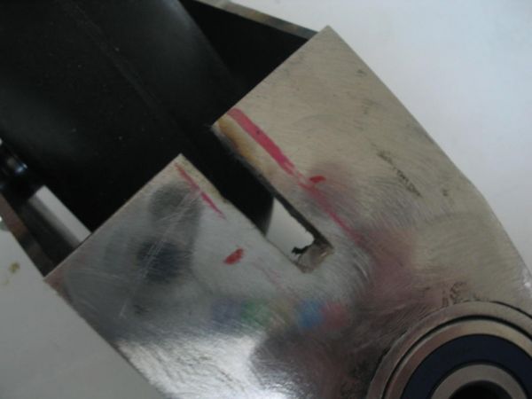
ANyway, I cut a notch in the previously welded assembly. This notch is for the latch.I was careful not to cut it too deep (toward the bearing). This is because if the cablethat will hold the lock mechanism were to fail, the lock mechanism cannot drop all the way down low enough to interfere with the wheel rotation.
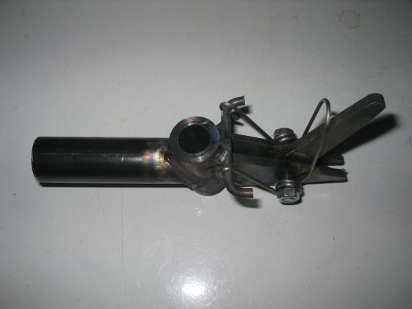
Next up was the top piece. The triangle parts were cut from .125 4130 steel, the locking mechanism was cut from .200 4130 steel, the spring retainer piece at the top is 3/16 4130 rod, and the tubing is 1"OD x .500 ID, drilled to accept bolts and spring rod mounting. I welded the spring rod mount on a 10deg angle.
The little latch spring is made from 17-7 PH stainless, .078 OD. Bending this stuff to shape is not easy, but it's spring qualities are excellent for this application.
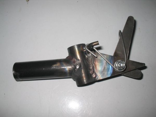
I must also mention that I cut some 5/16OD bushings to go over the bolt where the spring winds around. I also used a shoulder bolt cut to size so that the triangles are not pinched together when the bolt is tightened. Bolt pictured is not bolt used.
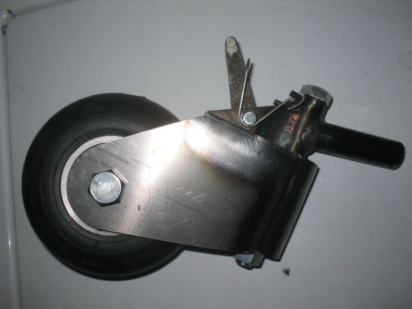
Below is the finished unit. Yea, it looks like a familiar tailwheel sold commercially. My has some differences:
I used a 6" cushion wheel instead of a flat wheel. It's the same type wheel Steen uses on their assembly, so I figgure it's gotta work OK. Again, I'm not an engineer so I errored on the side of safety....stronger is better, just not lighter.
Mine has a latch that will not drop into the rotating wheel....others don't.
Mine has bearings instead of bushings. I must mention that the bearing I chose, a radialball bearing, has an axial load rating sufficient for this application. However, a tapered roller bearing would be a better idea and I might just go to that type. I used a 1633 radial ball bearing. ATimken tapered roller bearing #4A and #6 have the sameOD on the bearing cup, but the cone ID is a bit larger necessitating the use of a larger bolt.
Any questions and constructive criticisms are always welcome.
Edited by: scottly
My goal was to get this thing as light as a Scott 3200, which is about 7lbs.... but the Scott 3200 uses a heavier leaf spring and I am using spring rod. If I can get my wheel to 7lbs, I'll be a happy camper.
I think it is as heavy as it is because of the bulky material I used. Since I am not an engineer and don't know about stress analysis, I built this thing with great amount of overkill in mind. I know it's safe, it's just heavier than I'd like it to be.
ANyway, I cut a notch in the previously welded assembly. This notch is for the latch.I was careful not to cut it too deep (toward the bearing). This is because if the cablethat will hold the lock mechanism were to fail, the lock mechanism cannot drop all the way down low enough to interfere with the wheel rotation.
Next up was the top piece. The triangle parts were cut from .125 4130 steel, the locking mechanism was cut from .200 4130 steel, the spring retainer piece at the top is 3/16 4130 rod, and the tubing is 1"OD x .500 ID, drilled to accept bolts and spring rod mounting. I welded the spring rod mount on a 10deg angle.
The little latch spring is made from 17-7 PH stainless, .078 OD. Bending this stuff to shape is not easy, but it's spring qualities are excellent for this application.
I must also mention that I cut some 5/16OD bushings to go over the bolt where the spring winds around. I also used a shoulder bolt cut to size so that the triangles are not pinched together when the bolt is tightened. Bolt pictured is not bolt used.
Below is the finished unit. Yea, it looks like a familiar tailwheel sold commercially. My has some differences:
I used a 6" cushion wheel instead of a flat wheel. It's the same type wheel Steen uses on their assembly, so I figgure it's gotta work OK. Again, I'm not an engineer so I errored on the side of safety....stronger is better, just not lighter.
Mine has a latch that will not drop into the rotating wheel....others don't.
Mine has bearings instead of bushings. I must mention that the bearing I chose, a radialball bearing, has an axial load rating sufficient for this application. However, a tapered roller bearing would be a better idea and I might just go to that type. I used a 1633 radial ball bearing. ATimken tapered roller bearing #4A and #6 have the sameOD on the bearing cup, but the cone ID is a bit larger necessitating the use of a larger bolt.
Any questions and constructive criticisms are always welcome.
Edited by: scottly