


Ok, Idler arm is complete. My plans call for a bushing-type set up. Steen sells one with a bearing, much like the McKenzie design. The plans and the MacKenzie news letters do not show an angle for the shaft. The new part being shipped by Steen is angled to clear the rib truss.
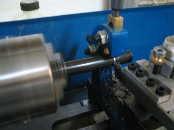
The first pic shows the lathe cutting the tubing needed for the newly designed bearing tube. You'll need to cut (with precision) 3/4" x .065 4130 tubing to 1.750", 5/8" x .065 4130 tubing to 1.360, and 3/8" x .065 4130 tubing to 1.360. So, this will give you the outer bearing tube (3/4"), the pressed-in sleeve (5/8"), and the compression bushing (3/8").
You'll then need to drill a 1/4" hole in the bearing housing. This will be for a rosete weld. Be careful where you drill this...if you place the hole properly, you'll be able to hide the weld in the opening of the 5/8" square tubing.
Ream the inside of the bearing housing to .625. This will allow fitment of bearing and sleeve.
Press sleeve into bearing housing. Make sure you center it from end to end. To assist you, you may with to use a bearing on one end to take up the proper space.
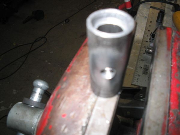
You'll end up with something like the above pic.
Next, rosette weld the inner sleeve to the outer housing.
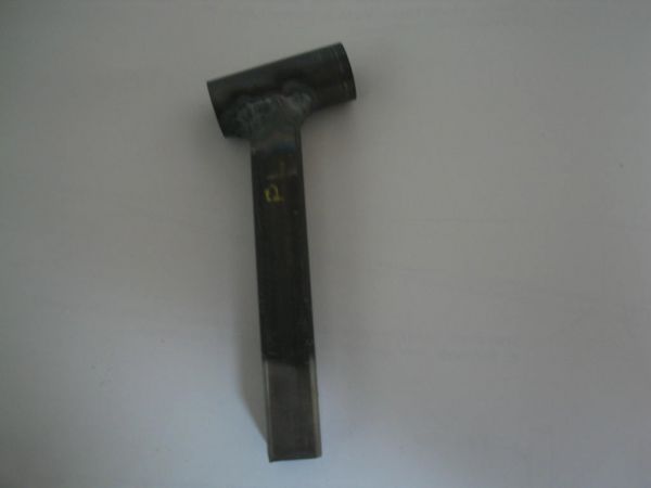
Next, bevel the edge of the 5/8" square tubing 10degrees. Either use a hole saw or a grinder to cut a pocket for the bearing housing to fit into. It will be welded together at this angle. It will look something like this when done:
Clean up the other end to prepare for welding of the plates.
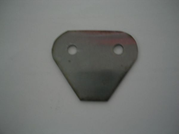
The plates shown in the newsletters are .071. The plans plates are .063. I used .063 for my plates. Use your own judgement....They lolok like this when done:
Welding the plates: Since I made my own idler arm brackets, and there can be minute differences in sizing when bending metal, I decided to match each Idler Arm with it's own bracket. What I mean by that is this: The center hole int he plates should be 6" from the spar plate the idler bracket mounts on.
So, I installed the partially assembled idler arm into the idler arm bracket and measures, then marked where I was going to place the plates.
I then welded the plates on. I ended up with this:
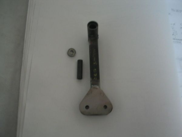
The bearing used is an R4zz. The dimensions are .250 x .625 x .196.
I will powedercoat and install bearings on each end.
If you got this far, please leave a comment.... Does this post help you? Bother you? Confuse you? Make you want to quit? Make you want to tell me to quit?
Say something!!!!!!!!!!")
The first pic shows the lathe cutting the tubing needed for the newly designed bearing tube. You'll need to cut (with precision) 3/4" x .065 4130 tubing to 1.750", 5/8" x .065 4130 tubing to 1.360, and 3/8" x .065 4130 tubing to 1.360. So, this will give you the outer bearing tube (3/4"), the pressed-in sleeve (5/8"), and the compression bushing (3/8").
You'll then need to drill a 1/4" hole in the bearing housing. This will be for a rosete weld. Be careful where you drill this...if you place the hole properly, you'll be able to hide the weld in the opening of the 5/8" square tubing.
Ream the inside of the bearing housing to .625. This will allow fitment of bearing and sleeve.
Press sleeve into bearing housing. Make sure you center it from end to end. To assist you, you may with to use a bearing on one end to take up the proper space.
You'll end up with something like the above pic.
Next, rosette weld the inner sleeve to the outer housing.
Next, bevel the edge of the 5/8" square tubing 10degrees. Either use a hole saw or a grinder to cut a pocket for the bearing housing to fit into. It will be welded together at this angle. It will look something like this when done:
Clean up the other end to prepare for welding of the plates.
The plates shown in the newsletters are .071. The plans plates are .063. I used .063 for my plates. Use your own judgement....They lolok like this when done:
Welding the plates: Since I made my own idler arm brackets, and there can be minute differences in sizing when bending metal, I decided to match each Idler Arm with it's own bracket. What I mean by that is this: The center hole int he plates should be 6" from the spar plate the idler bracket mounts on.
So, I installed the partially assembled idler arm into the idler arm bracket and measures, then marked where I was going to place the plates.
I then welded the plates on. I ended up with this:
The bearing used is an R4zz. The dimensions are .250 x .625 x .196.
I will powedercoat and install bearings on each end.
If you got this far, please leave a comment.... Does this post help you? Bother you? Confuse you? Make you want to quit? Make you want to tell me to quit?
Say something!!!!!!!!!!