


AlRice
Well-Known Member
- Joined
- Aug 18, 2006
- Messages
- 262
- Reaction score
- 0
This is the 2nd installment on building a Skybolt fuselage. This step shows the how to fit the tailpost.
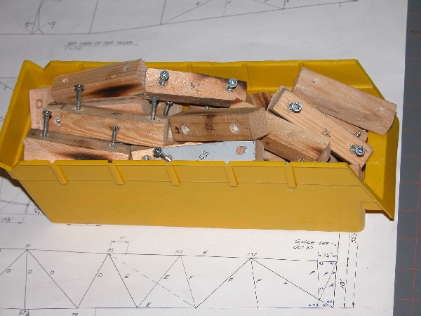
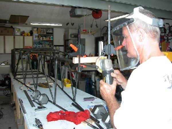
Before we get to the tailpost, here is a pic of about 100 jig blocks that are needed to locate and hold the fuselage tubes in place on the table. They are 3/4x3/4x3". Besides these jig blocks, you will also need several 1/16" shims to shim up smaller tubing to mate with larger tubing.
This is my collection jig alignment blocks. Notice that they are ripped in the same widths of all the tubing that is used in the fuselage. They also have a centerline at each end which is essential to align the blocks over top of the tube centerlines drawn on the table. To use alignment blocks, just hold them tightly in place centered exactly over the tube centerline, place a jig block tightly next to it and screw the jig block to the table.
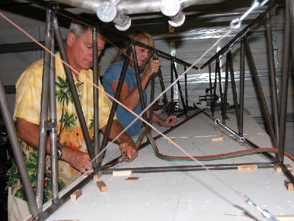
After I tack welded the top tubes at stations 0 and 51, and the bottom tubes at 0, 13, and 57 1/8, I heated and bent the longerons in toward the centerline at the tail. Notice that the fuselage is upside down and still jigged on the table. To accurately locate the bottom tubes at 0 and 51 since the fuselage is upside down, be sure to draw the lines on the table and drop a plumb bob down to the lines. Make every tube align perfectly with your lines on the table. Put a sheet of steel under station 57 1/8 so that you don't scorch your table. Alternate between heating and bending the top and bottom longerons and go slow! A helper is essential. You want all 4 longerons to perfectly meet at the tailpost without needing to be flexed in or out when tacking them to the tailpost. This will help keep you tailpost vertical.
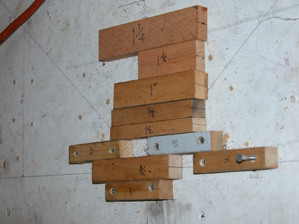
This is my jig that holds the tailpost perfectly vertical in both planes. It is made of 3/4" MDF and a 1x2 screwed on the backside at the bottom. Notice that I drilled a hole through the table for the tailpost. The jig is then screwed down to the table. Don't splice in the top half of the tailpost until you are ready to build the turtledeck and fin since it will just get in the way of spinning your fuselage on the rotisserie for welding.
Be sure to mark the tailpost notches in the longerons so that the centerlines of the upper longerons intersect no closer than the outside (tangent) of the tailpost to insure that there will be enough clearance between the upper longerons for the elevator arm and pushrod. I used my trusty 4" grinder and cheapo die grinder to do the job. Notice that I tack welded the top tube at station 85 (and the bottom tube at station 79) to help keep the longerons aligned while fitting the tailpost.
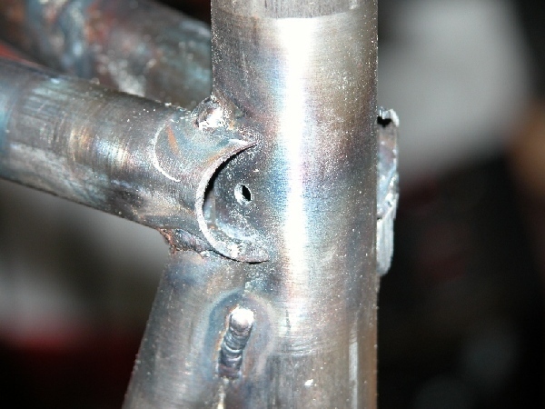
Here is the longeron/tail joint when it is done. Tack weld the tail post while it is securely in the jig. Notice the 1/8" hole for rust preventative oil circulation.
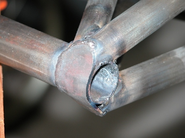
Finally, I finished off the joint with a .063" reinforcing strap around the tailpost. To do this, just tack at one end, heat the strap, bend it, then tack at the other end, and grind flush. This is the bottom where the tailwheel bracket gets mounted. The top strap is done the same way. This is not the way shown in the plans, but I feel that it is a little stronger and gives a little more steel to weld the tailwheel bracket to.
Edited by: AlRice